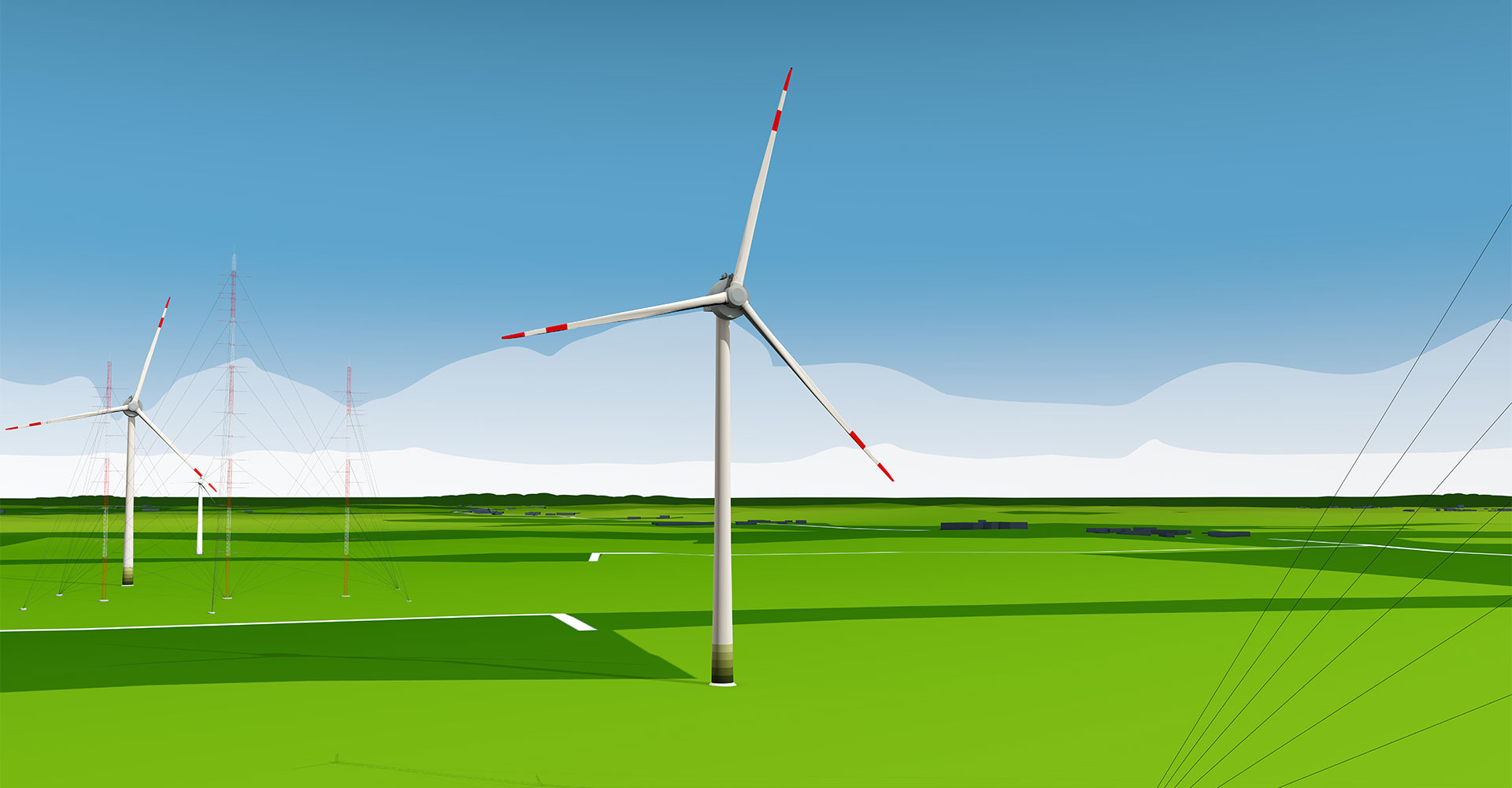
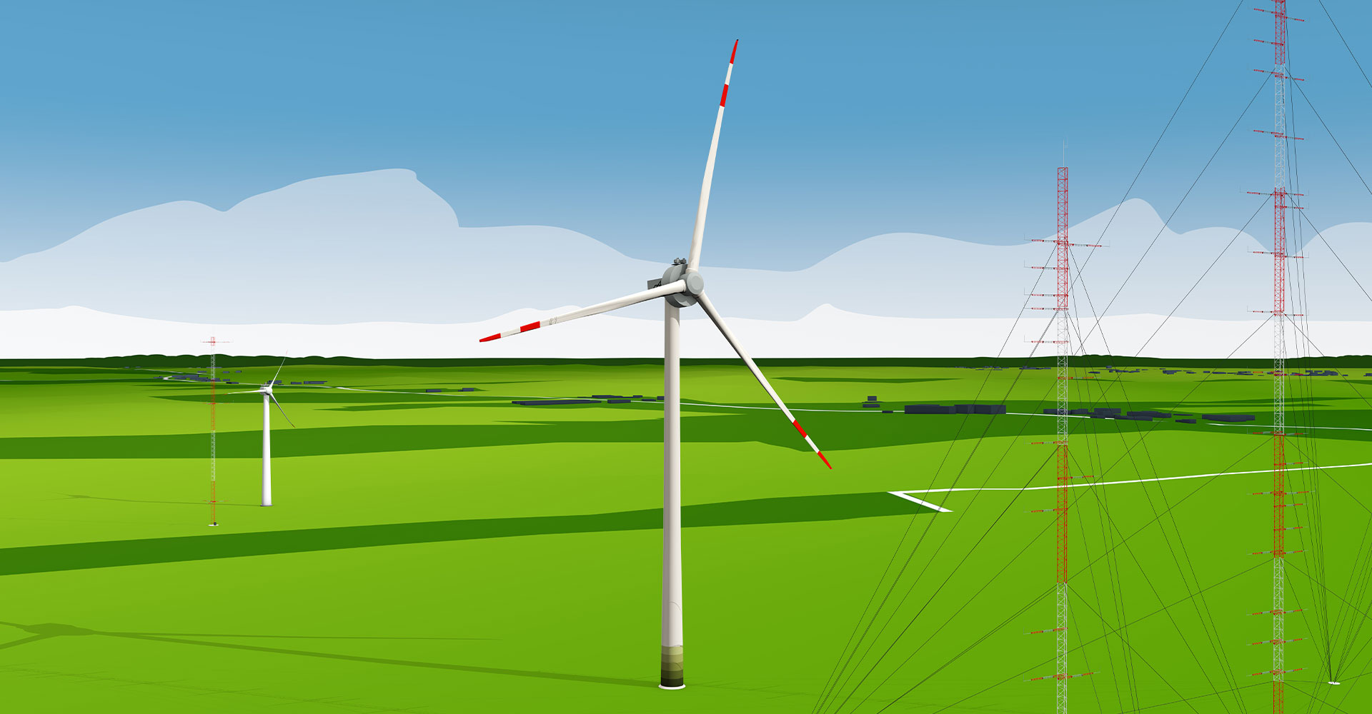
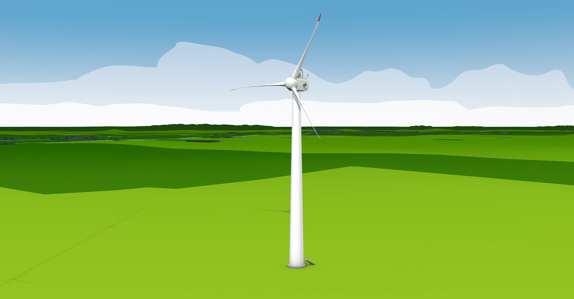
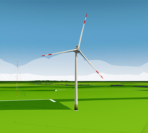
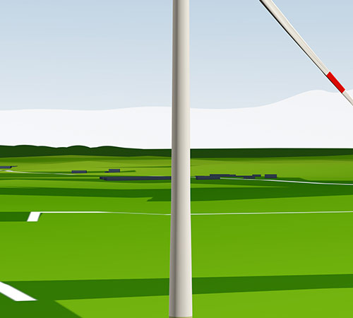
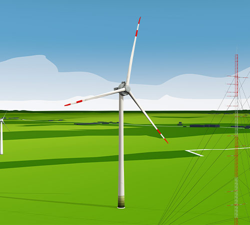
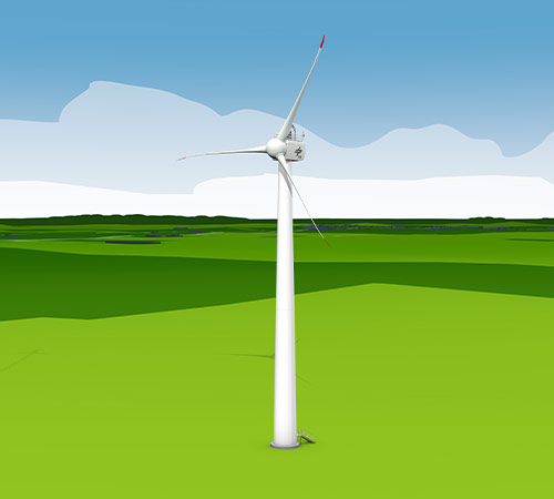
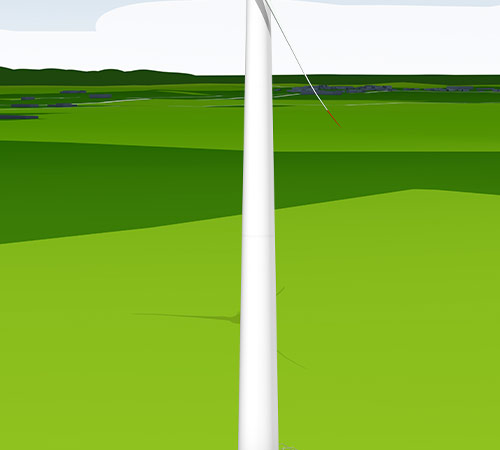
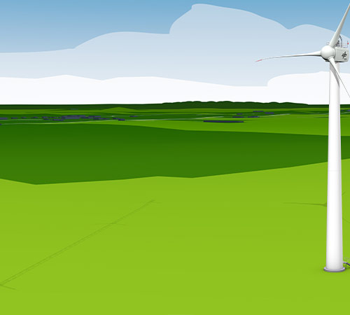
OPUS 1 and OPUS 2 are identical wind turbines, each with a total height of 150 metres and a rotor diameter of 116 metres. However, the turbines are instrumented differently.
Show details
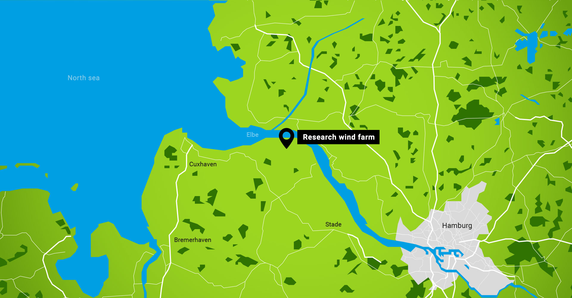
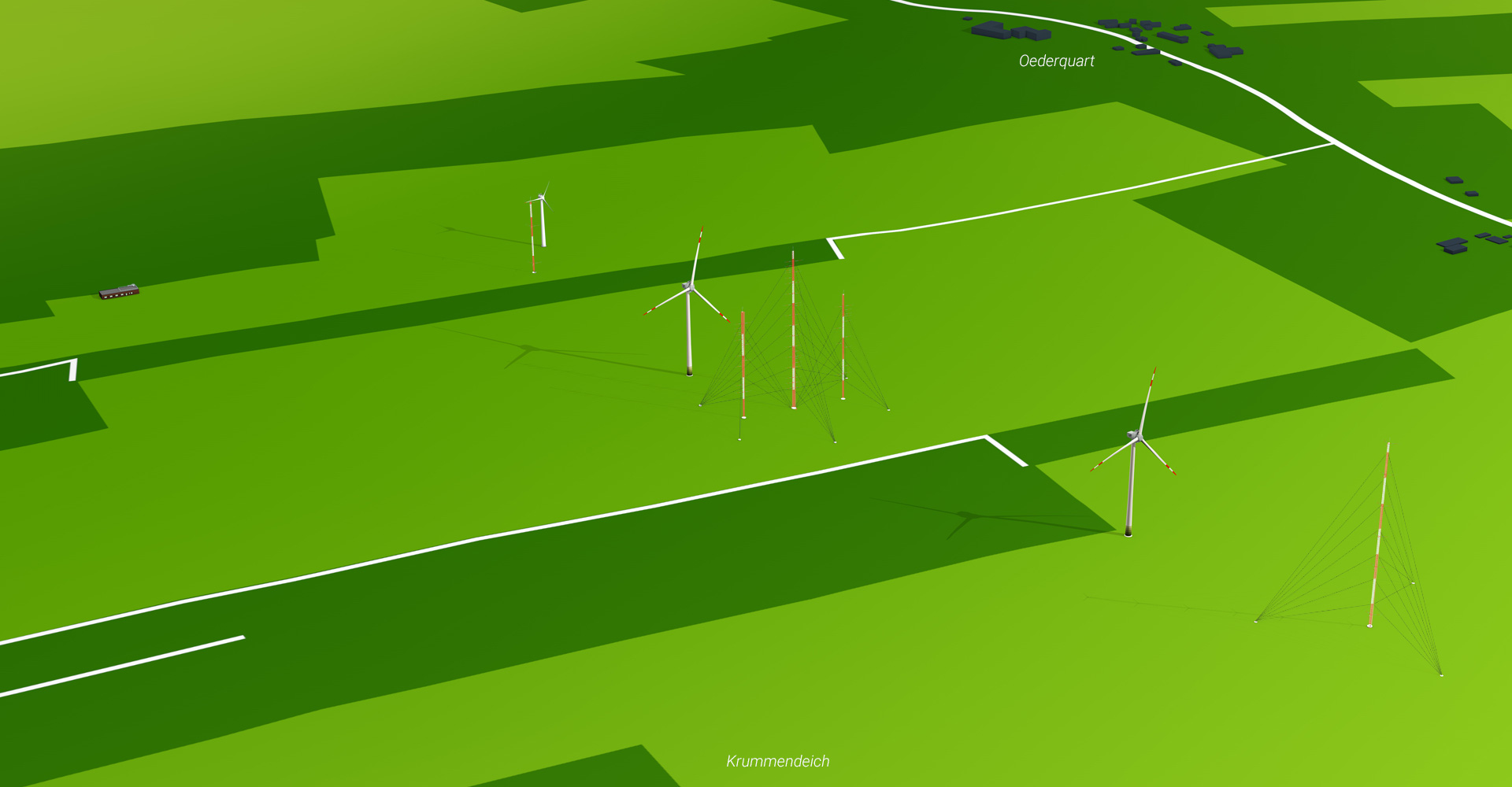
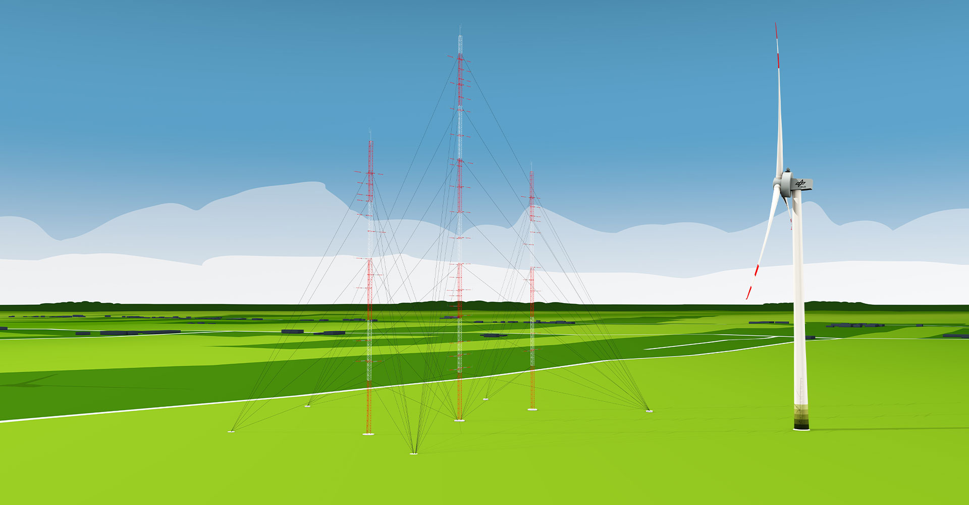
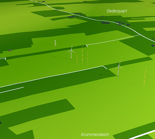
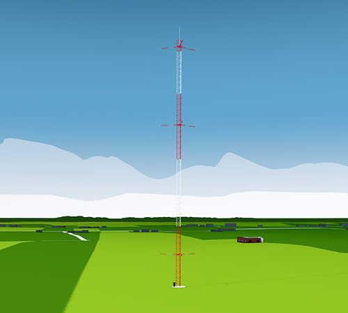
Valuable data for science and research is collected at the research wind farm in Krummendeich. The research facility consists of a total of three wind turbines: two state-of-the-art wind turbines OPUS 1 and OPUS 2, which are flanked by meteorological Measurement mast 1 and the Measurement mast array, and a smaller WTG 3, which is complemented by Measurement mast 5. Additional instrumentation will be installed at the windfarm for specific campaigns. The data from the research facility is prepared and processed in the Control center.
Interactive infographic
Click on the terms to get more information.
OPUS 1 and OPUS 2 are identical wind turbines, each with a total height of 150 metres and a rotor diameter of 116 metres. However, the turbines are instrumented differently.
OPUS 1 and OPUS 2 are identical wind turbines, each with a total height of 150 metres and a rotor diameter of 116 metres. However, the turbines are instrumented differently.
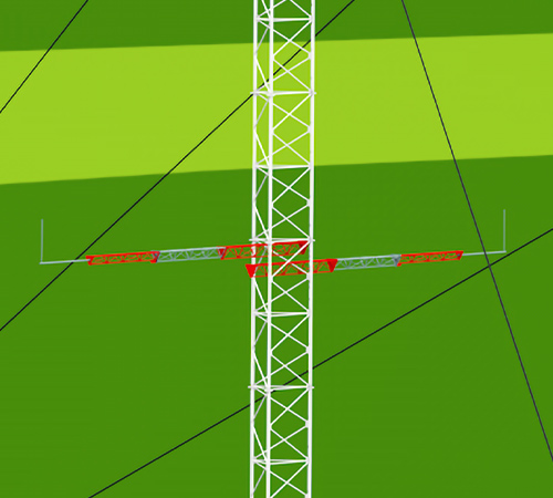
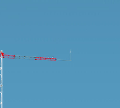
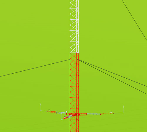
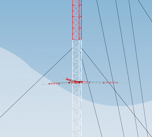
MEASUREMENT MAST ARRAY
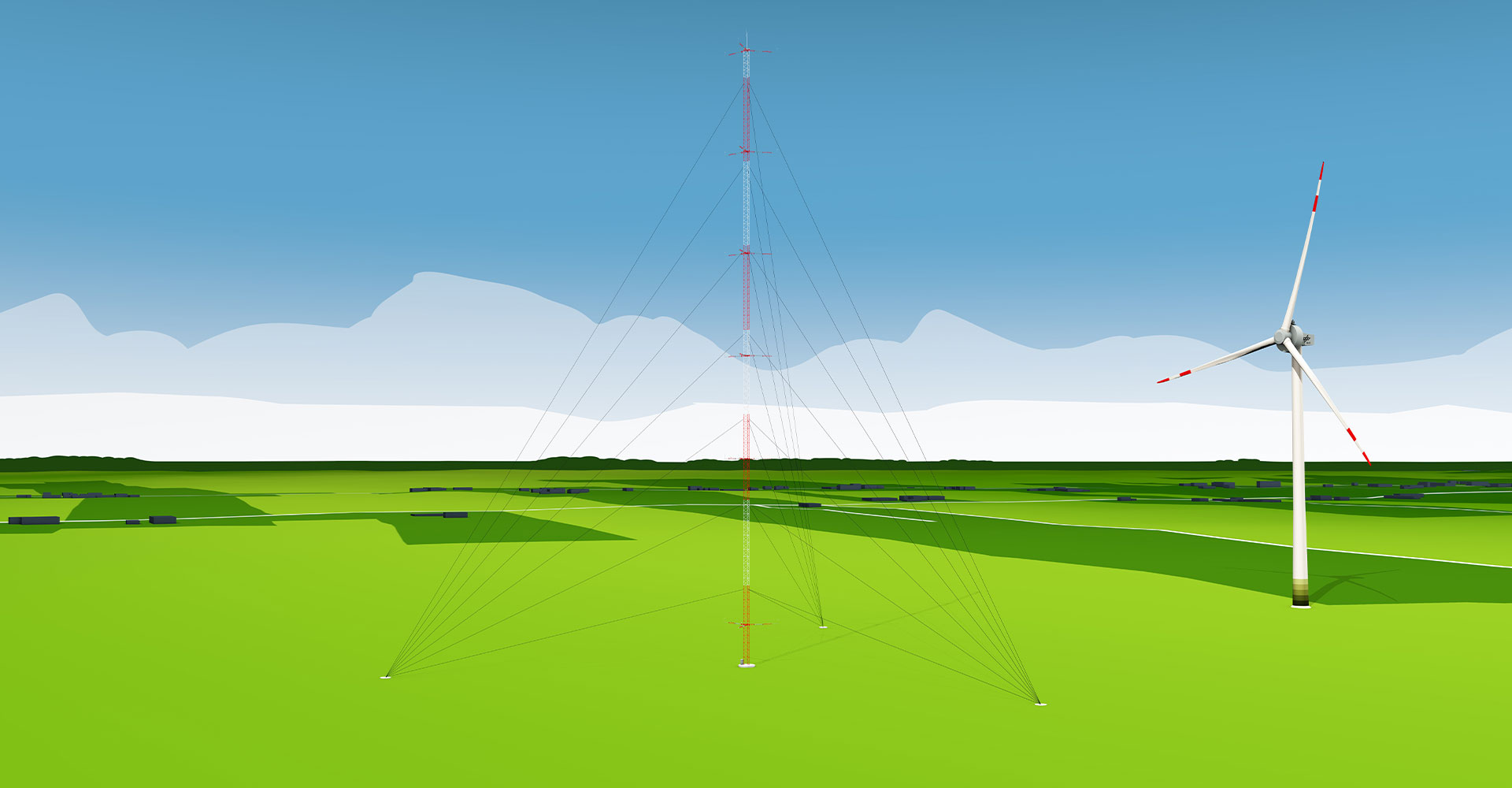
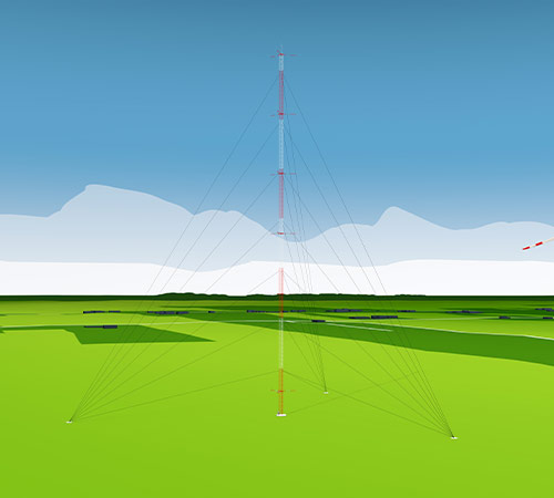
The measurement mast array consists of three masts; the outer two are 100 metres high, the centre one is 150 metres high. They are each equipped with a comprehensive array of meteorological sensors. The special configuration of the booms and measurement instruments on these three masts makes it possible to particularly effectively record the turbulence generated by OPUS 1, which has a significant influence on the inflow to OPUS 2.
WTG 3
WTG 3 is a wind turbine adapted and modifiable for research experiments, with specially developed rotor blades. It has a maximum output of 500 kW and a hub height of 50 metres.
MEASUREMENT MAST 1
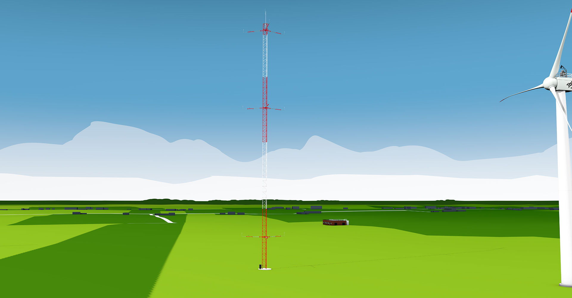
The IEC plus measurement mast is equipped with the necessary measurement technologies to carry out certification measurements in accordance with the IEC 61400 standard. In addition, it is equipped with extensive additional instrumentation to be able to measure the wind field flowing into OPUS 1 from the ground up to the rotor blade tips at a height of 150 metres.
MEASUREMENT MAST 5
In order to determine the local wind conditions at WTG 3, it has its own 70-metre-tall measurement mast. This is used to record a wide range of meteorological parameters.
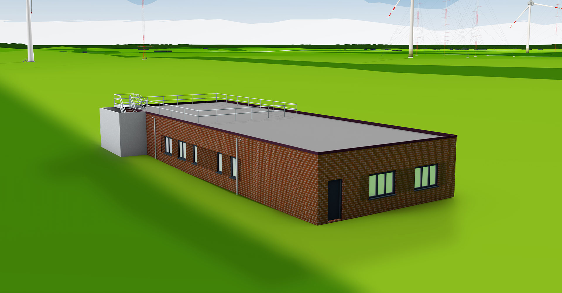
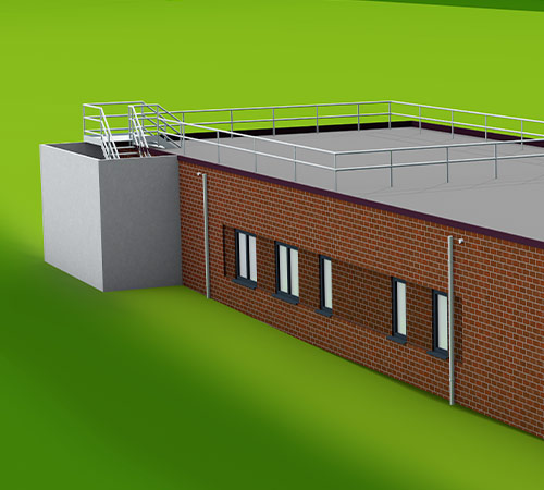
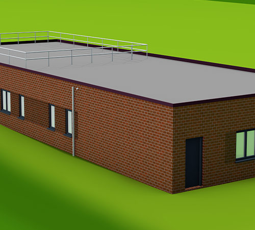
CONTROL CENTER
All the data generated by the research wind farm are collected in this building. The data from the sensors are processed here. The control room is the centre for on-site work – whether in the office, the workshop or the laboratory
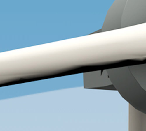
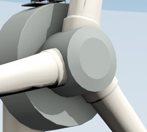
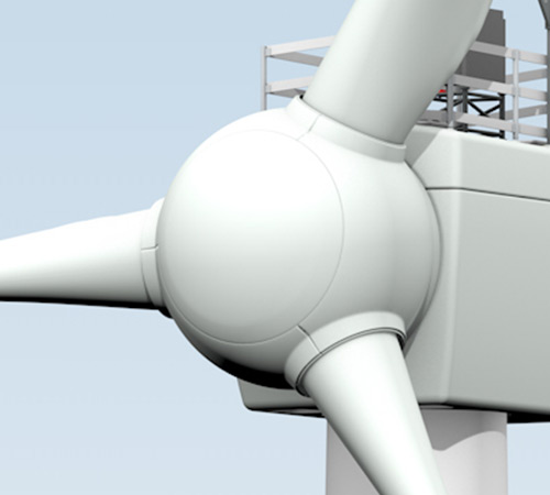
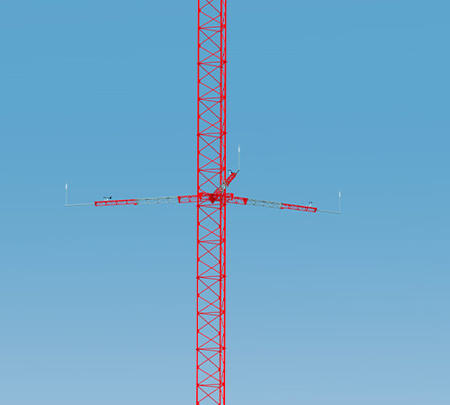
NACELLE
The nacelle contains all the electrical components of the wind turbine. This design employs a gearless drive train – that is, the generator is driven directly by the rotor. Research instrumentation is used to measure important parameters on the generator, transformer and converter as well as other parts of the power electronics. In addition, a fully steerable LiDAR system is installed on top of the nacelle, with which the incoming wind and the wind field behind the rotor can be measured.
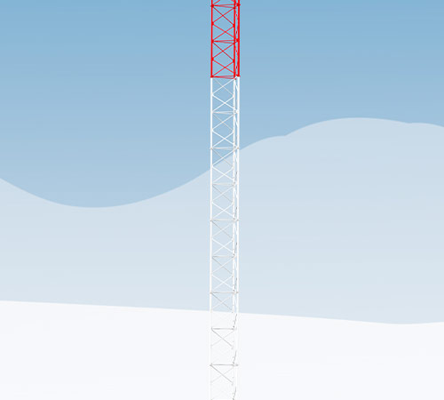
TOWER
In order to record the vibrations and deformations of the tower during both normal operations and in extreme situations (for example, during an emergency stop), acceleration and strain sensors are installed at various heights. The forces acting on the fastenings connecting the tower segments are also recorded.
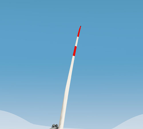
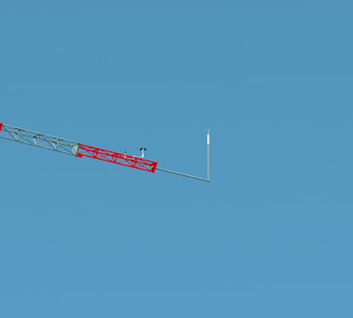
ROTOR BLADES
The rotor blades are equipped with comprehensive sensors to precisely analyze their behavior in the wind. Many different sensor systems can characterize the rotor blade in detail. The knowledge about the rotor blade is necessary to optimize wind turbines in future research projects.
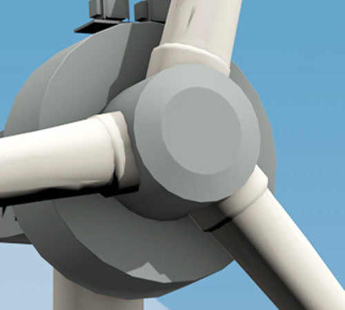
HUB
All cables from the sensors installed in the blades converge in the rotor hub. The measurement data are transferred from the rotating system to the fixed system in the nacelle by means of a slip ring and fibre-optic transmission system. In addition to a number of measurement systems, a rotating LiDAR system is also installed here, which records the wind conditions directly in front of the rotor.
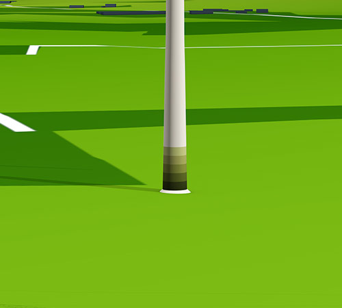
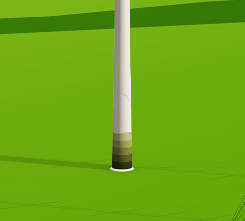
FOUNDATIONS
The tower is supported by a pile foundation system due to the nature of the underlying ground. Concrete piles up to 36 metres long support the tower. The piles of OPUS 1 are equipped with sensors to record the forces acting in its foundations.
NACELLE
The nacelle contains all the electrical components of the wind turbine. This design employs a gearless drive train – that is, the generator is driven directly by the rotor. Research instrumentation is used to measure important parameters on the generator, transformer and converter as well as other parts of the power electronics. In addition, a fully steerable LIDAR system is installed on top of the nacelle, with which the incoming wind and the wind field behind the rotor can be measured.
HUB
All cables from the sensors installed in the blades converge in the rotor hub. The measurement data are transferred from the rotating system to the fixed system in the nacelle by means of a slip ring and fibre-optic transmission system. In addition to a number of measurement systems, a rotating LIDAR system is also installed here, which records the wind conditions directly in front of the rotor.
TOWER
In order to record the vibrations and deformations of the tower during both normal operations and in extreme situations (for example, during an emergency stop), acceleration and strain sensors are installed at various heights. The forces acting on the fastenings connecting the tower segments are also recorded.
FOUNDATIONS
The tower is supported by a pile foundation system due to the nature of the underlying ground. Concrete piles up to 36 metres long support the tower.
ROTOR BLADES
The rotor blades are equipped with comprehensive sensors to precisely analyze their behavior in the wind. Many different sensor systems can characterize the rotor blade in detail. The knowledge about the rotor blade is necessary to optimize wind turbines in future research projects.
TOWER
The steel tower consists of two segments and has additional reinforcement compared to a standard design in order to increase its rigidity and to achieve a higher natural frequency. As the tower undergoes less distortion due to this design, safe experimental operations are possible.
NACELLE
WTG 3 has a semi-integrated drivetrain where some components have been separated and is equipped with an adapted gearbox. The drive train is significantly oversized for the rotor blades and is therefore very robust and especially suitable for experiments with overload conditions. A crane on the nacelle roof enables quick and straightforward replacement of individual components. The drive train is designed to operate the wind turbine in both left-handed and right-handed rotation, as well as upwind and downwind.
ROTOR BLADES
The rotor blades have a particularly slender shape to enable aeroelastic phenomena to be studied. In addition, the blade tips are interchangeable. This means that the blades can be quickly and easily converted to suit a wide range of experiments.
CRANE INSTALLATION AREA
The fixed crane installation area of WTG 3 is particularly large in order to have enough working space available for possible modifications, such as a blade changes.
HUB
The hub is designed to allow the installation of different rotor blades. The entire hub can also be exchanged, for example to enable the operation of a two-blade rotor. The hub is equipped with mounting points for a blade inspection system, with which the rotor blade can be inspected, maintained or instrumented over its entire length.
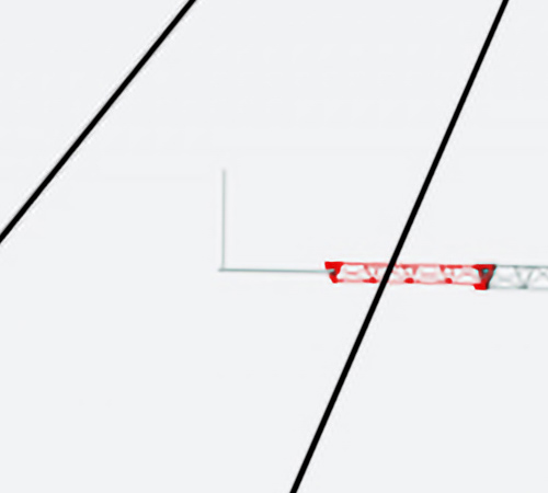
BOOMS
The measurement masts have numerous booms at different heights and of various lengths, on which the sensors are installed. The booms can be retracted for instrument installation.
PLATFORM
Approximately halfway up the centre mast is a platform designed for the installation of a LIDAR system. This platform can also be used for alternative instrumentation and is equipped with a hoist for this purpose.
CONFIGURATION
The three measurement masts are orthogonal to the prevailing wind direction, so that they can perform measurements across a vertical surface directly between OPUS 1 and OPUS 2 with the instruments on their booms when the wind comes from this direction. This allows the turbulent wind field behind OPUS 1 to be accurately measured before it arrives at OPUS 2 and interacts with the rotor blades there. Due to the special arrangement of the measurement instruments on the up to nine-metre-long booms, both large-scale phenomena, such as wind shear (that is, when the wind blows more strongly at higher elevations) and smaller events such as turbulence or vortices can be detected very well.
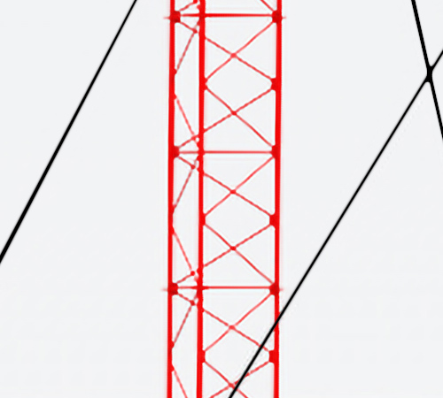
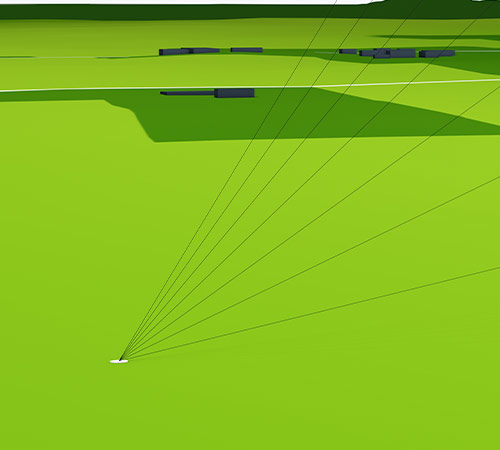
GUY WIRES
The masts in the measurement array are guyed lattice mast constructions. The guy wires run in three directions and each consist of five to seven steel cables that are attached to anchor points. The guy wires of the smaller and the larger masts are partly attached to the same anchor points. The fixings on the anchor points are elevated so that a clearance height suitable for agriculture is achieved under the cables as close as possible to the anchors.
BOOMS
The measurement mast has set of three booms located at a total of seven measurement heights distributed along the length of the mast between 10 and 140 metres, on which most of the sensors are installed. The booms can be retracted for instrument installation.
METEOROLOGICAL SENSORS
Since this measuring mast is IEC compliant and is approved for certification measurements on the wind turbines, the positions of the basic sensors for measuring wind speed, wind direction and temperature are precisely specified. In order to meet the much higher requirements of research, it is also equipped with extensive additional instrumentation up to a measurement height of 150 metres, the maximum blade tip height of the wind turbines at the site.
STRUCTURE
Numerous acceleration sensors are installed on the mast structure to record the movements of the very slender mast and the forces acting on the guy wires and the foundations.
GUY WIRES
The measurement mast is a guyed lattice mast construction. The guy wires run in three directions and each set consists of seven steel cables that are attached to an anchor point. The fixings on the anchor points are elevated so that a clearance height suitable for agriculture is achieved under the cables as close as possible to the anchors.
BOOMS
The measurement mast has numerous booms at different heights and of various lengths, on which the sensors are installed. The booms can be retracted for instrument installation.
METEOROLOGICAL SENSOR TECHNOLOGIES
This measurement mast is equipped with extensive meteorological sensing technologies to determine the wind conditions at the experimental turbine. Primarily, cup anemometers and ultrasonic anemometers are used, but also temperature and humidity sensors. There is also the possibility of attaching further, specialised sensor technologies to the measurement mast as part of test or validation campaigns.
STRUCTURE
Due to its low height, this measurement mast does not need guy wires. Numerous acceleration sensors are installed on the mast to reliably record the movements of the very slender mast and the forces acting on its foundations.
LABORATORY
Here, it is possible to carry out smaller-scale scientific work or prepare experiments. The researchers have the opportunity to carry out work in the direct vicinity of the wind turbines.
WORKSHOP
In the workshop, large-scale technical work such as repairs or modifications can be carried out. Smaller spare parts are stored here in order to be able to react flexibly to the demands of a wide variety of research projects.
OFFICE SPACE
Researchers can work here with the usual on-site infrastructure or meet with project partners. Office workstations, a meeting room and social areas are available.
DATA MANAGEMENT SYSTEM
All data generated by the wind turbines, the measurement masts and the field instrumentation are provided with a highly accurate time stamps and fed into the central on-site data management system. There, the data is temporarily stored in a fail-safe manner and transferred to the archive data management system located in the DLR computer centre, which makes the data available online for retrieval and further processing.
Accelerometers
The sensors measure the acceleration occurring at a specific point to calculate the leaf vibration. The use of both electrical and fiber optic acceleration sensors at different points enables a clear detection of the vibrations regarding the entire rotor blade.
Ultrasonic sensors
These sensors enable Structural Health Monitoring (SHM). SHM is a method to monitor certain components of the wind turbine (usually in the rotor blades) regarding their flawless condition, so that cracks or other damage are immediately detected and localized. Among other things, a piezoelectric sensor network is used for this purpose.
Fiber Optic Strain Sensors
The sensors enable the optical transmission of the measured variable. A light source (usually laser or LED) is connected to a fiber optic cable (e.B. glass fiber) and a detector. The optical properties of the optical fiber are changed by the desired measured variable (e.B. polarizability, fluorescence, absorption). With the help of this principle the load distribution of the entire rotor blade can be determined.
Strain gauges
Strain gauges are installed in many different spots within the rotor blade. The small adhesive strips can detect a change in the length of the carrier material by means of electrical resistance and thus precisely detect the occuring forces.
BladeVision
The optical sensor system monitors the deflection of the rotor blades. For this purpose, mirrors are distributed over the length of the rotor blade. From the root of the rotor blade, a laser beam is sent to these mirrors. Depending on the deflection of the blade, the angle of the reflected laser beam changes.
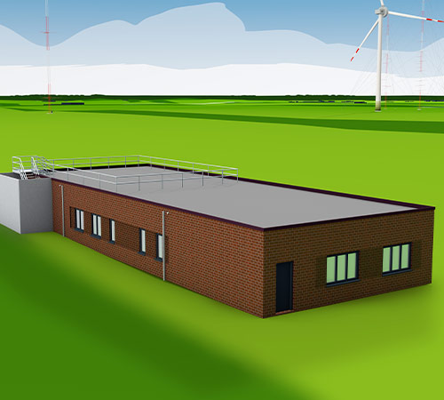
All the data generated by the research wind farm are collected in this building. The data from the sensors are processed here. The control room is the centre for on-site work – whether in the office, the workshop or the laboratory.
OFFICE SPACE
Researchers can work here with the usual on-site infrastructure or meet with project partners. Office workstations, a meeting room and social areas are available.
LABORATORY
Here, it is possible to carry out smaller-scale scientific work or prepare experiments. The researchers have the opportunity to carry out work in the direct vicinity of the wind turbines.
WORKSHOP
In the workshop, large-scale technical work such as repairs or modifications can be carried out. Smaller spare parts are stored here in order to be able to react flexibly to the demands of a wide variety of research projects.
DATA MANAGEMENT SYSTEM
All data generated by the wind turbines, the measurement masts and the field instrumentation are provided with a highly accurate time stamps and fed into the central on-site data management system. There, the data is temporarily stored in a fail-safe manner and transferred to the archive data management system located in the DLR computer centre, which makes the data available online for retrieval and further processing.
OPUS 1 and OPUS 2 are identical wind turbines, each with a total height of 150 metres and a rotor diameter of 116 metres. However, the turbines are instrumented differently.
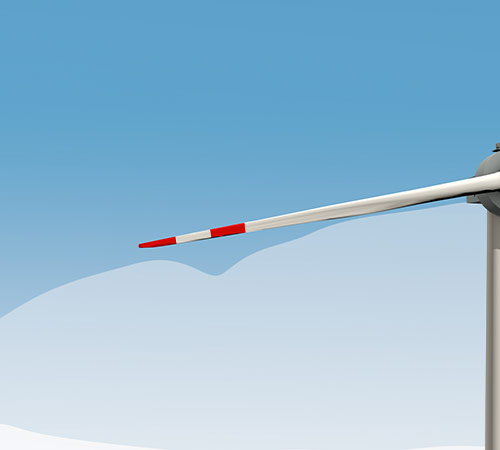
ROTOR BLADES
The rotor blades are equipped with comprehensive sensors to precisely analyze their behavior in the wind. Many different sensor systems can characterize the rotor blade in detail. The knowledge about the rotor blade is necessary to optimize wind turbines in future research projects.
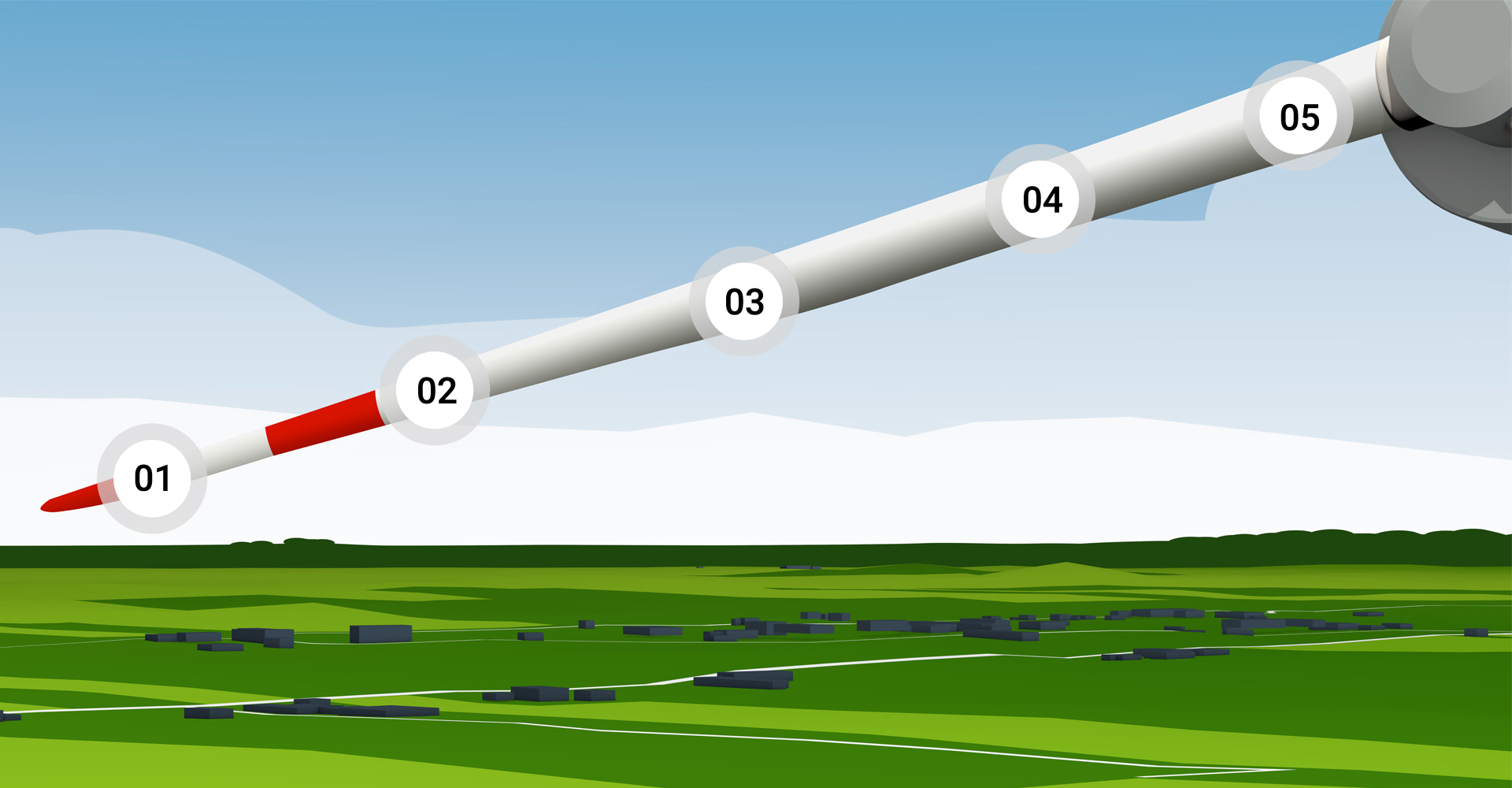
01 Accelerometers
The sensors measure the acceleration occurring at a specific point to calculate the leaf vibration. The use of both electrical and fiber optic acceleration sensors at different points enables a clear detection of the vibrations regarding the entire rotor blade.
02 Ultrasonic sensors
These sensors enable Structural Health Monitoring (SHM). SHM is a method to monitor certain components of the wind turbine (usually in the rotor blades) regarding their flawless condition, so that cracks or other damage are immediately detected and localized. Among other things, a piezoelectric sensor network is used for this purpose.
03 Fiber Optic Strain Sensors
The sensors enable the optical transmission of the measured variable. A light source (usually laser or LED) is connected to a fiber optic cable (e.B. glass fiber) and a detector. The optical properties of the optical fiber are changed by the desired measured variable (e.B. polarizability, fluorescence, absorption). With the help of this principle the load distribution of the entire rotor blade can be determined.
04 Strain gauges
Strain gauges are installed in many different spots within the rotor blade. The small adhesive strips can detect a change in the length of the carrier material by means of electrical resistance and thus precisely detect the occuring forces.
05 BladeVision
The optical sensor system monitors the deflection of the rotor blades. For this purpose, mirrors are distributed over the length of the rotor blade. From the root of the rotor blade, a laser beam is sent to these mirrors. Depending on the deflection of the blade, the angle of the reflected laser beam changes.
NACELLE
The nacelle contains all the electrical components of the wind turbine. This design employs a gearless drive train – that is, the generator is driven directly by the rotor. Research instrumentation is used to measure important parameters on the generator, transformer and converter as well as other parts of the power electronics. In addition, a fully steerable LiDAR system is installed on top of the nacelle, with which the incoming wind and the wind field behind the rotor can be measured.
HUB
All cables from the sensors installed in the blades converge in the rotor hub. The measurement data are transferred from the rotating system to the fixed system in the nacelle by means of a slip ring and fibre-optic transmission system. In addition to a number of measurement systems, a rotating LIDAR system is also installed here, which records the wind conditions directly in front of the rotor.
TOWER
In order to record the vibrations and deformations of the tower during both normal operations and in extreme situations (for example, during an emergency stop), acceleration and strain sensors are installed at various heights. The forces acting on the fastenings connecting the tower segments are also recorded.
FOUNDATIONS
The tower is supported by a pile foundation system due to the nature of the underlying ground. Concrete piles up to 36 metres long support the tower. The piles of OPUS 1 are equipped with sensors to record the forces acting in its foundations.
OPUS 1 and OPUS 2 are identical wind turbines, each with a total height of 150 metres and a rotor diameter of 116 metres. However, the turbines are instrumented differently.
Rotor blades
The rotor blades are equipped with comprehensive sensors to precisely analyze their behavior in the wind. Many different sensor systems can characterize the rotor blade in detail. The knowledge about the rotor blade is necessary to optimize wind turbines in future research projects.
01 Accelerometers
The sensors measure the acceleration occurring at a specific point to calculate the leaf vibration. The use of both electrical and fiber optic acceleration sensors at different points enables a clear detection of the vibrations regarding the entire rotor blade.
02 Ultrasonic sensors
These sensors enable Structural Health Monitoring (SHM). SHM is a method to monitor certain components of the wind turbine (usually in the rotor blades) regarding their flawless condition, so that cracks or other damage are immediately detected and localized. Among other things, a piezoelectric sensor network is used for this purpose.
03 Fiber Optic Strain Sensors
The sensors enable the optical transmission of the measured variable. A light source (usually laser or LED) is connected to a fiber optic cable (e.B. glass fiber) and a detector. The optical properties of the optical fiber are changed by the desired measured variable (e.B. polarizability, fluorescence, absorption). With the help of this principle the load distribution of the entire rotor blade can be determined.
04 Strain gauges
Strain gauges are installed in many different spots within the rotor blade. The small adhesive strips can detect a change in the length of the carrier material by means of electrical resistance and thus precisely detect the occuring forces.
05 BladeVision
The optical sensor system monitors the deflection of the rotor blades. For this purpose, mirrors are distributed over the length of the rotor blade. From the root of the rotor blade, a laser beam is sent to these mirrors. Depending on the deflection of the blade, the angle of the reflected laser beam changes.
NACELLE
The nacelle contains all the electrical components of the wind turbine. This design employs a gearless drive train – that is, the generator is driven directly by the rotor. Research instrumentation is used to measure important parameters on the generator, transformer and converter as well as other parts of the power electronics. In addition, a fully steerable LIDAR system is installed on top of the nacelle, with which the incoming wind and the wind field behind the rotor can be measured.
HUB
All cables from the sensors installed in the blades converge in the rotor hub. The measurement data are transferred from the rotating system to the fixed system in the nacelle by means of a slip ring and fibre-optic transmission system. In addition to a number of measurement systems, a rotating LIDAR system is also installed here, which records the wind conditions directly in front of the rotor.
TOWER
In order to record the vibrations and deformations of the tower during both normal operations and in extreme situations (for example, during an emergency stop), acceleration and strain sensors are installed at various heights. The forces acting on the fastenings connecting the tower segments are also recorded.
FOUNDATIONS
The tower is supported by a pile foundation system due to the nature of the underlying ground. Concrete piles up to 36 metres long support the tower.
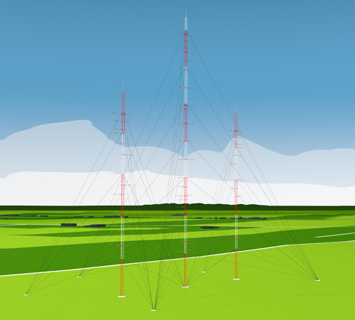
The measurement mast array consists of three masts; the outer two are 100 metres high, the centre one is 150 metres high. They are each equipped with a comprehensive array of meteorological sensors. The special configuration of the booms and measurement instruments on these three masts makes it possible to particularly effectively record the turbulence generated by OPUS 1, which has a significant influence on the inflow to OPUS 2.
CONFIGURATION
The three measurement masts are orthogonal to the prevailing wind direction, so that they can perform measurements across a vertical surface directly between OPUS 1 and OPUS 2 with the instruments on their booms when the wind comes from this direction. This allows the turbulent wind field behind OPUS 1 to be accurately measured before it arrives at OPUS 2 and interacts with the rotor blades there. Due to the special arrangement of the measurement instruments on the up to nine-metre-long booms, both large-scale phenomena, such as wind shear (that is, when the wind blows more strongly at higher elevations) and smaller events such as turbulence or vortices can be detected very well.
GUY WIRES
The masts in the measurement array are guyed lattice mast constructions. The guy wires run in three directions and each consist of five to seven steel cables that are attached to anchor points. The guy wires of the smaller and the larger masts are partly attached to the same anchor points. The fixings on the anchor points are elevated so that a clearance height suitable for agriculture is achieved under the cables as close as possible to the anchors.
BOOMS
The measurement masts have numerous booms at different heights and of various lengths, on which the sensors are installed. The booms can be retracted for instrument installation.
PLATFORM
Approximately halfway up the centre mast is a platform designed for the installation of a LIDAR system. This platform can also be used for alternative instrumentation and is equipped with a hoist for this purpose.
WTG 3 is a wind turbine adapted and modifiable for research experiments, with specially developed rotor blades. It has a maximum output of 500 kW and a hub height of 50 metres.
ROTOR BLADES
The rotor blades have a particularly slender shape to enable aeroelastic phenomena to be studied. In addition, the blade tips are interchangeable. This means that the blades can be quickly and easily converted to suit a wide range of experiments.
NACELLE
WTG 3 has a semi-integrated drivetrain where some components have been separated and is equipped with an adapted gearbox. The drive train is significantly oversized for the rotor blades and is therefore very robust and especially suitable for experiments with overload conditions. A crane on the nacelle roof enables quick and straightforward replacement of individual components. The drive train is designed to operate the wind turbine in both left-handed and right-handed rotation, as well as upwind and downwind.
TOWER
The steel tower consists of two segments and has additional reinforcement compared to a standard design in order to increase its rigidity and to achieve a higher natural frequency. As the tower undergoes less distortion due to this design, safe experimental operations are possible.
CRANE INSTALLATION AREA
The fixed crane installation area of WTG 3 is particularly large in order to have enough working space available for possible modifications, such as a blade changes.
HUB
The hub is designed to allow the installation of different rotor blades. The entire hub can also be exchanged, for example to enable the operation of a two-blade rotor. The hub is equipped with mounting points for a blade inspection system, with which the rotor blade can be inspected, maintained or instrumented over its entire length.
The IEC plus measurement mast is equipped with the necessary measurement technologies to carry out certification measurements in accordance with the IEC 61400 standard. In addition, it is equipped with extensive additional instrumentation to be able to measure the wind field flowing into OPUS 1 from the ground up to the rotor blade tips at a height of 150 metres.
GUY WIRES
The measurement mast is a guyed lattice mast construction. The guy wires run in three directions and each set consists of seven steel cables that are attached to an anchor point. The fixings on the anchor points are elevated so that a clearance height suitable for agriculture is achieved under the cables as close as possible to the anchors.
BOOMS
The measurement mast has set of three booms located at a total of seven measurement heights distributed along the length of the mast between 10 and 140 metres, on which most of the sensors are installed. The booms can be retracted for instrument installation.
STRUCTURE
Numerous acceleration sensors are installed on the mast structure to record the movements of the very slender mast and the forces acting on the guy wires and the foundations.
METEOROLOGICAL SENSORS
Since this measuring mast is IEC compliant and is approved for certification measurements on the wind turbines, the positions of the basic sensors for measuring wind speed, wind direction and temperature are precisely specified. In order to meet the much higher requirements of research, it is also equipped with extensive additional instrumentation up to a measurement height of 150 metres, the maximum blade tip height of the wind turbines at the site.
In order to determine the local wind conditions at WTG 3, it has its own 70-metre-tall measurement mast. This is used to record a wide range of meteorological parameters.
BOOMS
The measurement mast has numerous booms at different heights and of various lengths, on which the sensors are installed. The booms can be retracted for instrument installation.
STRUCTURE
Due to its low height, this measurement mast does not need guy wires. Numerous acceleration sensors are installed on the mast to reliably record the movements of the very slender mast and the forces acting on its foundations.
METEOROLOGICAL SENSOR TECHNOLOGIES
This measurement mast is equipped with extensive meteorological sensing technologies to determine the wind conditions at the experimental turbine. Primarily, cup anemometers and ultrasonic anemometers are used, but also temperature and humidity sensors. There is also the possibility of attaching further, specialised sensor technologies to the measurement mast as part of test or validation campaigns.
The research wind farm in Krummendeich is funded by the Federal Ministry for Economic Affairs and Energy (BMWE) and the Lower Saxony Ministry of Science and Culture (MWK).